4 Buttons on 1 Analog Pin: The Voltage Divider Trick for Arduino
Most Arduino tutorials wire one button per digital pin. Fine, until you also need a sensor, a motor driver, and an OLED. Pins run out fast.
This trick puts four push buttons on a single analog pin using a resistor ladder. Each button produces a different voltage on A0. The sketch reads the value, finds the closest calibrated match, and tells you which key was pressed.
Key Takeaways
- The pin has to be an analog input (
A0toA7on the Arduino Uno). The trick reads a continuous voltage, not HIGH/LOW.- Four buttons share that pin via four resistors with binary-ish values: 1 kΩ, 2.2 kΩ, 4.7 kΩ, 10 kΩ.
- Ohm’s law (
V = R·I) does the work. Each resistor drops a different share of the 5 V, so the pin sees a unique voltage per button.- A 1 kΩ pull-down to ground keeps the pin at 0 V when nothing is pressed, so the reading is stable.
- The sketch picks the closest threshold within a ±20-point tolerance. Average several samples per check if the line is noisy.
- You free three digital pins for sensors, motors, or displays.
Why an analog pin (and what the ADC is doing)
Buttons have to sit on A0 (or any pin in A0 to A7 on the Uno) because we’re reading a specific voltage level, not a binary state. Digital pins can’t do that. They only see “above the logic threshold” or “below it”, and we need more resolution than two buckets.
Each analog pin on the Arduino is wired to an ADC, an analog-to-digital converter. The ADC samples the voltage on the pin and maps it to a 10-bit integer:
- Input range: 0 V to 5 V (or whatever
AREFis set to) - Output range: 0 to 1023 (10 bits is 2¹⁰ values)
- Resolution: roughly 4.9 mV per step
So when analogRead(A0) returns 510, the pin is sitting at about 510 / 1023 × 5 V ≈ 2.49 V. The whole point of the resistor network is to put each button’s voltage far enough from the others that the ADC’s integer output lands in a clean bucket.
How the circuit works
The four buttons sit in parallel between 5 V and the analog input. Each button has its own series resistor:
| Button | Series resistor |
|---|---|
| 1 | 1 kΩ |
| 2 | 2.2 kΩ |
| 3 | 4.7 kΩ |
| 4 | 10 kΩ |
A fifth resistor, 1 kΩ to ground, is the pull-down. Together with whichever button-resistor is currently in circuit, it forms a voltage divider .
The intuition is just Ohm’s law (V = R·I). Press a button and 5 V is applied across two resistors in series: the button’s series resistor and the 1 kΩ pull-down. The same current flows through both, so each resistor drops a share of the 5 V proportional to its value. Bigger series resistor, bigger drop, less voltage left over at the pin. That’s why a 10 kΩ button lands near 0.45 V while a 1 kΩ button lands near 2.5 V.
The output voltage at A0 follows the standard divider formula:
Vout = Vin × Rpulldown / (Rpulldown + Rbutton)With Vin = 5 V and Rpulldown = 1 kΩ:
| Button pressed | R series | V at A0 | analogRead (0-1023) |
|---|---|---|---|
| 1 | 1 kΩ | ~2.50 V | ~510 |
| 2 | 2.2 kΩ | ~1.56 V | ~320 |
| 3 | 4.7 kΩ | ~0.88 V | ~180 |
| 4 | 10 kΩ | ~0.45 V | ~93 |
| none | - | 0 V | ~0 |
The values are spaced so that resistor tolerance, contact resistance, and ADC noise can’t push one reading into the next bucket.
The resistor choice is approximate, not exact powers of two. What matters is well-separated voltage levels. The ratios above give you four clean buckets even with ±5% resistors.
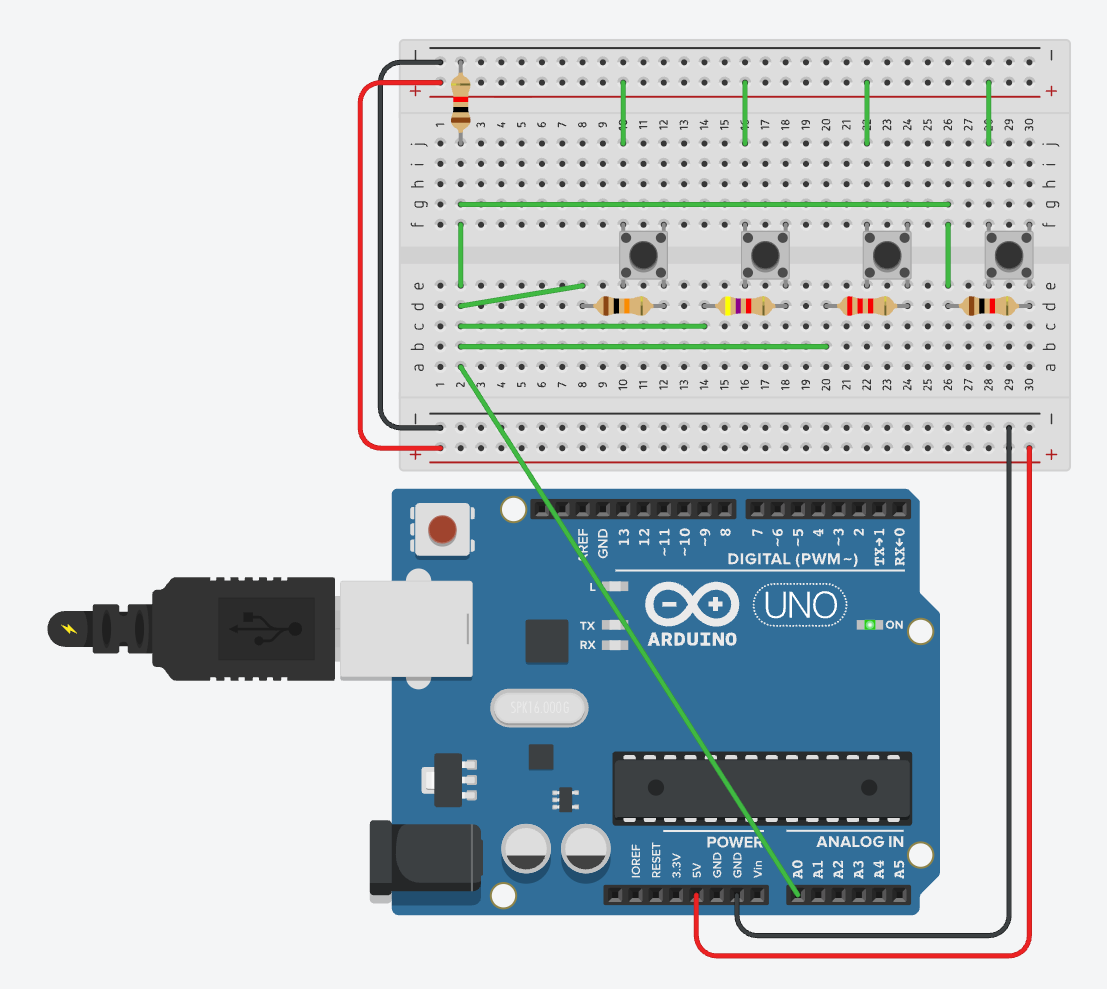
The schematic
Top rail is 5 V, bottom rail is GND. Each button bridges the 5 V rail to a column that holds its dedicated resistor. All four resistor outputs converge on the column wired to A0. The pull-down sits between that same column and GND.
Reading it from software
The sketch samples A0, finds the closest calibrated threshold, and only accepts the match when it’s within ±20 points. That tolerance window is what makes the matching robust to small drift.
It also does a debounce lock: once a press is registered, the loop blocks until the voltage drops back to zero, then waits 50 ms for the mechanical bounce to settle. No press is reported twice.
const int sensorPin = A0;

// The 4 calibrated base values
int thresholds[4] = {499, 314, 172, 90};
int buttonNames[4] = {1, 2, 3, 4};

void setup() {
  // Initialize serial communication at 9600 bits per second
  Serial.begin(9600);
  Serial.println("--- 4-Button Serial Keypad Ready ---");
}

void loop() {
  int reading = analogRead(sensorPin);

  // If reading is over 10, the 5V is getting through (a button is pressed)
  if (reading > 10) {

    int bestMatch = -1;
    int smallestDiff = 1024; // Start with the maximum possible difference

    // Scan the 4 thresholds to find the absolute closest one
    for (int i = 0; i < 4; i++) {
      int diff = abs(reading - thresholds[i]);
      if (diff < smallestDiff) {
        smallestDiff = diff;
        bestMatch = i;
      }
    }

    // Accept it only if the closest match is within the +/- 20 point tolerance
    if (smallestDiff <= 20) {

      // Print the matched button to the Serial Monitor
      Serial.print("Button Pressed: ");
      Serial.println(buttonNames[bestMatch]);

      // --- The Debounce Lock ---
      // Freeze the loop here until the voltage drops back to 0 (button released)
      while(analogRead(sensorPin) > 10) {
        delay(10);
      }

      // Pause for 50ms to ignore the mechanical spring physically bouncing
      delay(50);
    }
  }
}Calibrate your thresholds
The thresholds[4] values in the sketch are what I measured on my board. Yours will be off by a few points. Resistor tolerance, supply voltage, and ADC reference all shift the numbers a little.
Easiest calibration: flash a stripped-down sketch that just prints analogRead(sensorPin) on a loop. Press each button, write down the reading, paste those four numbers into the array. Done.
Average a few samples for noisy environments
A single analogRead() call can jitter by a few points from sample to sample. Long jumper wires, a noisy power supply, or anything switching nearby will all push the noise floor up. The ±20 tolerance window absorbs most of it, but if you see false matches near the edges of two ranges, take several readings and average them:
int readAveraged(int pin, int samples) {
  long total = 0;
  for (int i = 0; i < samples; i++) {
    total += analogRead(pin);
  }
  return total / samples;
}

// then in loop():
int reading = readAveraged(sensorPin, 8);Eight samples take about 1 ms total on the Uno (each analogRead is roughly 100 µs), and the noise floor drops a lot because random ADC error averages toward zero. This is independent of the debounce lock. Debouncing handles the mechanical bounce of the switch contacts; averaging handles the electrical noise on the line. Different problems, both worth solving.
Why the pull-down matters
Without the 1 kΩ to ground, the analog pin is floating when nothing is pressed. A floating ADC input picks up stray voltages from nearby traces and even your hand near the board, and the reading drifts unpredictably. You get phantom button presses.
The pull-down ties the pin firmly to 0 V whenever no button completes the circuit. The ADC reads a stable zero, the if (reading > 10) guard rejects it, and nothing happens. That single resistor is what separates a working keypad from one that fires randomly.
What you trade
The trick isn’t free.
- You lose multi-press detection unless you also calibrate the combined-press voltages. Pressing two buttons at once puts their resistors in parallel and produces a fifth, sixth, etc. distinct voltage. Doable, but the threshold table grows fast.
- One ADC sample takes about 100 µs on the Uno. If you need microsecond-level input timing, dedicated digital interrupts win. For UI buttons it doesn’t matter.
- Resistor drift in extreme heat or cold can push a reading outside the ±20 tolerance. Indoor projects are fine.
For menu navigation, mode switches, retro-game keypads, anything where buttons exist to drive a UI, one analog pin and five resistors is a much better deal than burning four digital pins.
Source
This post is the long-form companion to the YouTube short embedded in the sidebar (60 seconds, same circuit).
Thanks to a reader on the YouTube comments who pushed me to be clearer on the ADC side. The analogRead mapping from voltage to a 10-bit integer, the Ohm’s law framing for the voltage drop, and the multi-sample averaging trick all came out of that nudge.